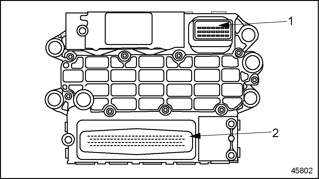
The engine mounted Motor Control Module (MCM) includes control logic to provide overall engine management. See Figure "Motor Control Module" .
|
1. 21–pin Connector (OEM Responsibility) |
2. 120–pin Connector (Detroit Diesel Responsibility) |
Figure 1. Motor Control Module
Note: Do NOT ground the MCM. This can result in false codes being logged.
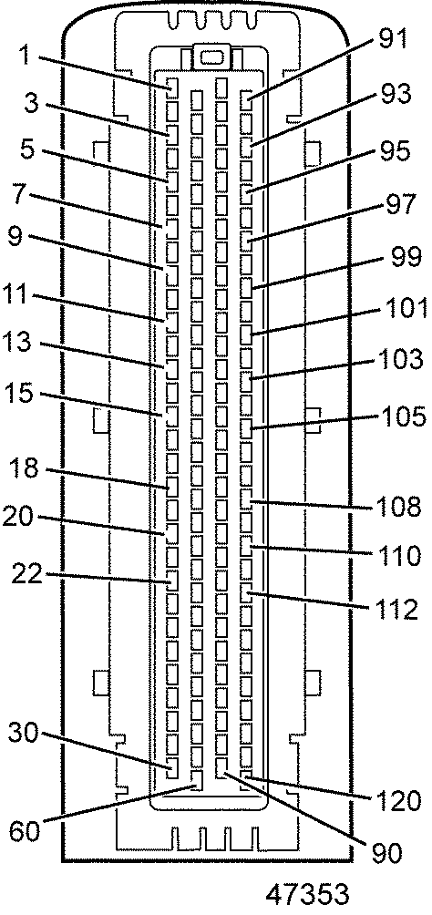
The MCM has a 120–pin connector Engine Harness which is factory installed. It also has a 21–pin connector which is the responsibility of the OEM. The pinouts for the 120–pin connector are listed in Table "MCM Connector – Series 60 (1 of 4)" , Table "MCM Connector – Series 60 (2 of 4) – C Sample" , Table "MCM Connector – Series 60 (3 of 4) – C Sample" , and Table "MCM Connector – Series 60 (4 of 4) – C Sample" .
The pinout for the 21–pin connector is listed in Table "21–Pin Connector to the MCM" .
|
Pin |
Function |
Connector |
|
1 |
NC |
|
|
2 |
NC |
|
|
3 |
NC |
|
|
4 |
Spill Control Valve (cyl 4) - pin 4 |
|
|
5 |
Spill Control Valve Common - pin 3 |
|
|
6 |
Spill Control Valve (cyl 6) - pin 4 |
|
|
7 |
Spill Control Valve Common - pin 3 |
|
|
8 |
Spill Control Valve (cyl 5) - pin 4 |
|
|
9 |
Spill Control Valve Common - pin 3 |
|
|
10 |
Spill Control Valve (cyl 2) - pin 4 |
 |
|
11 |
Spill Control Valve Common - pin 3 |
|
|
12 |
Spill Control Valve (cyl 3) - pin 4 |
|
|
13 |
NC |
|
|
14 |
Spill Control Valve (cyl 1) - pin 4 |
|
|
15 |
NC |
|
|
16 |
Needle Control Valve (cyl 4) - pin 2 |
|
|
17 |
Needle Control Valve Common - pin 1 |
|
|
18 |
Needle Control Valve (cyl 6) - pin 2 |
|
|
19 |
Needle Control Valve Common - pin 1 |
|
|
20 |
Needle Control Valve (cyl 5) - pin 2 |
|
|
21 |
Needle Control Valve Common - pin 1 |
|
|
22 |
Needle Control Valve (cyl 2) - pin 2 |
|
|
23 |
Needle Control Valve Common (cyl 1,2,3) - pin 1 |
|
|
24 |
Needle Control Valve (cyl 3) - pin 2 |
|
|
25 |
NC |
|
|
26 |
Needle Control Valve (cyl 1) - pin 2 |
|
|
27 |
NC |
|
|
28 |
NC |
|
|
29 |
DOC Outlet Temp Sensor |
|
|
30 |
DPF Outlet Pressure Sensor |
|
Pin |
Function |
Connector |
|
31 |
NC |
|
|
32 |
Jake 1 |
|
|
33 |
Two-speed Fan or Variable Speed Fan |
|
|
34 |
NC |
|
|
35 |
NC |
|
|
36 |
NC |
|
|
37 |
NC |
|
|
38 |
Ground |
|
|
39 |
NC |
|
|
40 |
NC |
|
|
41 |
NC |
|
|
42 |
CKP/TRS (-) |
|
|
43 |
CKP/TRS (+) |
|
|
44 |
CMP/SRS (-) |
|
|
45 |
CMP/SRS (+) |
|
|
46 |
NC |
|
|
47 |
Fan Speed |
|
|
48 |
NC |
|
|
49 |
NC |
|
|
50 |
Sensor Ground |
|
|
51 |
Turbo Speed Sensor |
|
|
52 |
Sensor Ground |
|
|
53 |
NC |
|
|
54 |
Engine Oil Pressure Sensor |
|
|
55 |
Sensor Ground |
|
|
56 |
NC |
|
|
57 |
NC |
|
|
58 |
Sensor Power Supply |
|
|
59 |
NC |
|
|
60 |
EGR Valve Position |
|
Pin |
Function |
Connector |
|
61 |
EGR Valve |
|
|
62 |
Power Supply |
|
|
63 |
NC |
|
|
64 |
Power Supply |
|
|
65 |
Doser |
|
|
66 |
Jake 2 |
|
|
67 |
Ground |
|
|
68 |
NC |
|
|
69 |
Fuel Cutoff Valve |
|
|
70 |
Ether Start |
|
|
71 |
NC |
|
|
72 |
NC |
|
|
73 |
NC |
|
|
74 |
VNT CAN (-) |
|
|
75 |
VNT CAN (+) |
|
|
76 |
NC |
|
|
77 |
Supply Fuel Temperature Sensor |
|
|
78 |
NC |
|
|
79 |
NC |
|
|
80 |
NC |
|
|
81 |
NC |
|
|
82 |
Sensor Supply |
|
|
83 |
EGR Temperature Sensor |
|
|
84 |
Fuel Compensation Pressure Sensor |
|
|
85 |
Sensor Supply |
|
|
86 |
Turbo Compressor In Temp |
|
|
87 |
Intake Manifold Pressure Sensor |
|
|
88 |
Sensor Ground |
|
|
89 |
DOC Inlet Temp Sensor |
|
|
90 |
Intake Air Throttle Valve |
|
Pin |
Function |
Connector |
|
91 |
Power Supply |
|
|
92 |
NC |
|
|
93 |
Power Supply |
|
|
94 |
NC |
|
|
95 |
NC |
|
|
96 |
NC |
|
|
97 |
NC |
|
|
98 |
Single-speed Fan or Two-speed Fan |
|
|
99 |
NC |
|
|
100 |
Intake Air Throttle (+) |
|
|
101 |
Intake Air Throttle (-) |
|
|
102 |
Sensor Ground |
|
|
103 |
Sensor Ground |
|
|
104 |
Sensor Ground |
|
|
105 |
Sensor Ground |
|
|
106 |
Intake Air Temperature Sensor |
|
|
107 |
NC |
|
|
108 |
Engine Oil Temperature Sensor |
|
|
109 |
EGR Delta Pressure Sensor |
|
|
110 |
Engine Coolant Temp Sensor |
|
|
111 |
Fuel Line Pressure Sensor |
|
|
112 |
Turbo Compressor Out Temp |
|
|
113 |
NC |
|
|
114 |
Sensor Ground |
|
|
115 |
DPF Outlet Temp Sensor |
|
|
116 |
NC |
|
|
117 |
Sensor Power Supply |
|
|
118 |
DPF Inlet Pressure Sensor |
|
|
119 |
NC |
|
|
120 |
NC |
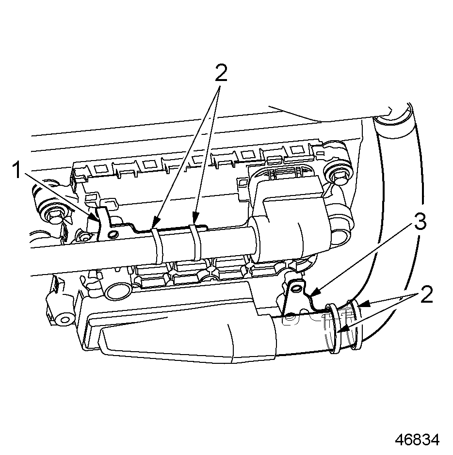
The harnesses on MCM must be bracketed and held secure. The bracket design will change for different engines as the routing is different. The 120–pin connector and the 21-pin connector must be tie-wrapped to the brackets as shown in the following drawing for the Series 60 engine (see Figure "Series 60 Engine 120–pin Connector and 21–pin Connector Tie-wrapped to Brackets" ).
|
1. 21–pin Connector Bracket |
3. 120–pin Connector Bracket |
|
2. Tie Wrap |
|
Figure 2. Series 60 Engine 120–pin Connector and 21–pin Connector Tie-wrapped to Brackets
The wiring for the VIH 21–pin to the MCM is listed in Table "21–Pin Connector to the MCM" . The side of the connector shown is looking into the pins.
|
Pin |
Signal Type |
Function |
Connector |
|
21/1 |
CAN2L |
Not Used |
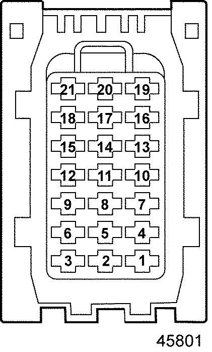 Front Looking into the Pins on the Harness |
|
21/2 |
CAN2GND |
Not Used |
|
|
21/3 |
CAN2H |
Not Used |
|
|
21/4 |
CAN2GND |
Not Used |
|
|
21/5 |
KL31 |
Battery (-) |
|
|
21/6 |
KL31 |
Battery (-) |
|
|
21/7 |
KL15 |
IGN |
|
|
21/8 |
KL31 |
Battery (-) |
|
|
21/9 |
KL31 |
Battery (-) |
|
|
21/10 |
CAN1GND |
Engine CAN Shield |
|
|
21/11 |
KL30 |
Battery (+) |
|
|
21/12 |
KL30 |
Battery (+) |
|
|
21/13 |
CAN1H |
Engine CAN + |
|
|
21/14 |
KL30 |
Battery (+) |
|
|
21/15 |
KL30 |
Battery (+) |
|
|
21/16 |
CAN1GND |
Not Used |
|
|
21/17 |
BOOT |
Not Used |
|
|
21/18 |
KDiag_S |
Not Used |
|
|
21/19 |
CAN1L |
Engine CAN – |
|
|
21/20 |
KL50 |
Crank Start Input |
|
|
21/21 |
START_B |
Crank Activation Output |
The pinout for the 31–pin pigtail on the Engine Harness is listed in Table "31–pin MCM Pigtail Connector" . The OEM is responsible for wiring to this connector.
|
31–pin |
120–pin |
Function |
Series 60 |
|
31/1 |
— |
Spare |
— |
|
31/2 |
— |
Power Supply (IGN)* |
— |
|
31/3 |
— |
Fuel Heater Supply #1† |
— |
|
31/4 |
— |
Spare |
— |
|
31/5 |
— |
Full Heater Supply #2† |
— |
|
31/6 |
— |
Spare |
— |
|
31/7 |
— |
Power Supply Ground* |
— |
|
31/8 |
120/70 |
Ether Start |
X |
|
31/9 |
120/33 |
Fan Control #2 – High of Two-speed Fan or Variable Speed Fan |
X |
|
31/10 |
120/98 |
Single Speed Fan or Low for Two-speed Fan |
X |
|
31/11 |
— |
Fuel Heater Ground #1† |
— |
|
31/12 |
— |
Spare |
— |
|
31/13 |
— |
Spare |
— |
|
31/14 |
120/71 |
Water-in-Fuel Sensor Supply |
— |
|
31/15 |
120/67 |
Water-in-Fuel Sensor Ground |
— |
|
31/16 |
120/96 |
Engine Brake Solenoid Control |
— |
|
31/17 |
120/29 |
DOC Outlet Temp Sensor (Exhaust Gas Temperature in Front of Particulate Trap) |
X |
|
31/18 |
120/89 |
DOC Inlet Temp Sensor |
X |
|
31/19 |
120/115 |
DPF Outlet Temp Sensor( Exhaust Gas Temperature After Particulate Trap) |
X |
|
31/20 |
— |
Full Heater Ground #2† |
— |
|
31/21 |
— |
Spare |
— |
|
31/22 |
120/91 |
Power Supply (Eng Brk, Fan, Ether) |
X |
|
31/23 |
120/47 |
Fan Speed |
X |
|
31/24 |
120/88 |
Sensor Ground |
X |
|
31/25 |
— |
Spare |
— |
|
31/26 |
120/57 |
Water-in-Fuel Sensor |
— |
|
31/27 |
120/86 |
TCI Temp |
X |
|
31/28 |
120/114 |
Sensor Ground |
X |
|
31/29 |
120/85 |
Sensor Supply |
X |
|
31/30 |
120/30 |
DPF Outlet Pressure Sensor (Exhaust Gas Pressure After Particulate Filter) |
X |
|
31/31 |
120/118 |
DPF Inlet Pressure Sensor (Exhaust Gas Pressure Before Particulate Filter) |
X |
| EPA07 Series 60 DDEC VI Troubleshooting Guide - 6SE567 |
| Generated on 10-13-2008 |