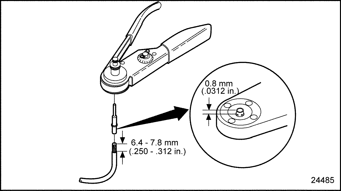
Figure 1. Setting Wire Gage Selector and Positioning the Contact
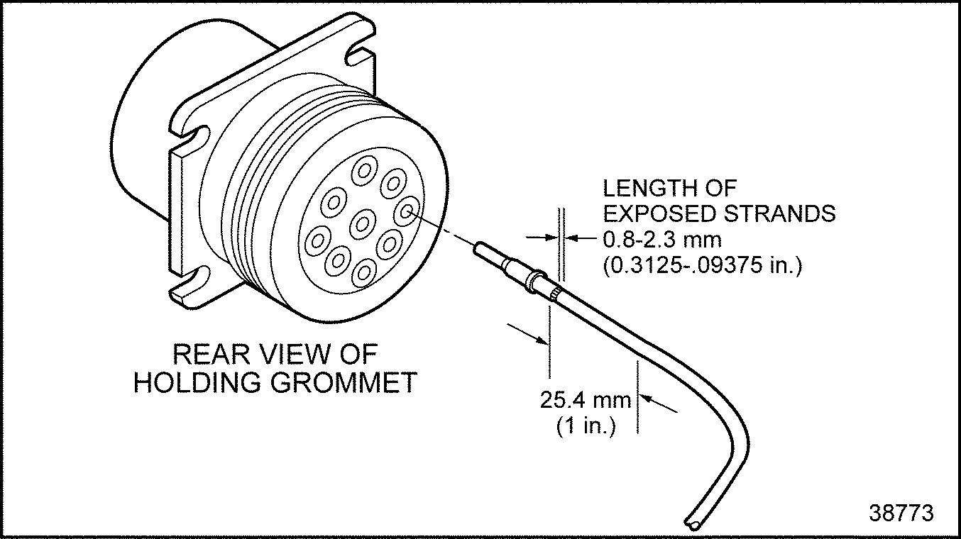
Figure 2. Pushing Contact Into Grommet
Detroit Diesel Corporation recommends color coding and hot stamping wire numbers in contrasting colors at intervals of four inches or less.
Note: Avoid renumbering DDC circuits since all troubleshooting guides reference the circuit numbers shown in the schematic. DDC suggests including a prefix or suffix with the DDC circuit numbers when conflicts exist.
All wires used in conjunction with DDEC VI must meet the following criteria:
NOTICE: |
|
DDC does not recommend using any type of terminal lubricant or grease compounds. These products may cause dirt or other harmful substances to be retained in the connector. DDC has not tested these products and cannot stand behind their use. |
NOTICE: |
|
Insulation must be free of nicks. |
The part numbers for the crimp tools for working with the MCM and CPC connectors are listed in Table "Crimp Tools" .
|
Description |
Part Number |
|
Extraction Tool |
726503–1 |
|
Hand Crimp Tool |
169400–0 |
|
Crimp Dies for 0.5 mm – 1.0 mm Terminals |
734262–0 |
|
Crimp Dies for 1.0 mm – 2.5 mm Terminals |
169917–0 |
The method of terminal installation and removal varies. The following sections cover Deutsch terminal installation and removal.
Deutsch connectors have cable seals molded into the connector. These connectors are push-to-seat connectors with cylindrical terminals. The diagnostic connector terminals are gold plated for clarity.
NOTICE: |
|
Improper selection and use of crimp tools have varying adverse effects on crimp geometry and effectiveness. Proper installation of terminals require specialized tools. Do not attempt to use alternative tools. |
The crimp tool to use in Deutsch terminal installation is J–34182 (Kent-Moore part number).
NOTICE: |
|
Terminal crimps must be made with the Deutsch crimp tool P/N: HDT-48-00 to assure gas tight connections. |
NOTICE: |
|
If a separate seal is required, be sure to install the seal onto the wire before stripping the insulation. |
Use the following instructions for installing Deutsch terminals:
Figure 1. Setting Wire Gage Selector and Positioning the Contact
Figure 2. Pushing Contact Into Grommet
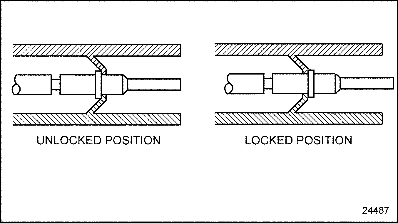
Figure 3. Locking Terminal Into Connector
The appropriate size removal tool should be used when removing cables from connectors. The proper removal tools are listed in Table "Removal Tools for Deutsch Terminals" .
|
Tool |
Kent-Moore Part Number |
|
Removing (12 AWG) |
J–37451 |
|
Removing (16-18 AWG) |
J–34513-1 |
Remove Deutsch terminals as follows:
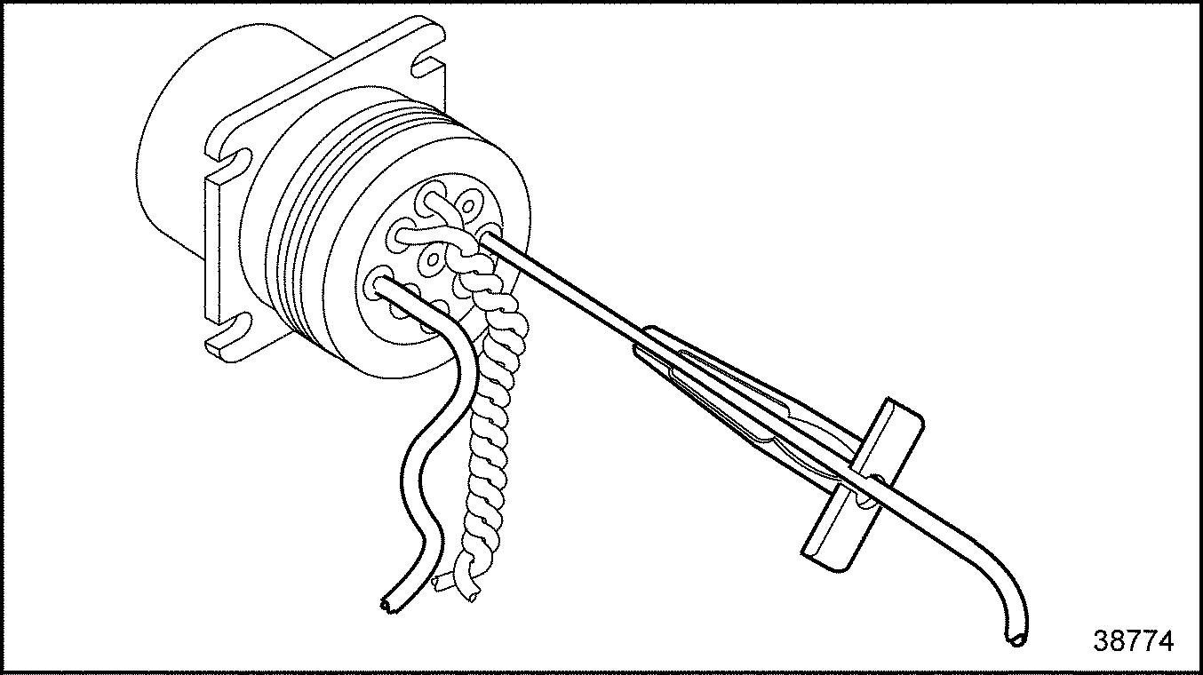
Figure 4. Removal Tool Position
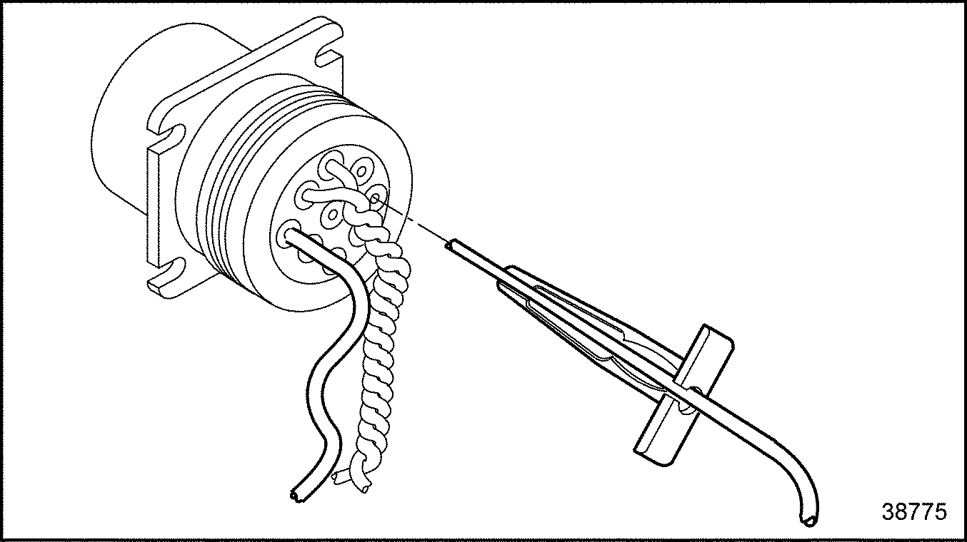
Figure 5. Removal Tool Insertion
The following are guidelines which may be used for splices. The selection of crimpers and splice connectors is optional. Select a high quality crimper equivalent to the Kent-Moore tool, J–38706, and commercially available splice clips.
The recommended technique for splicing and repairing circuits (other than power and ignition circuits) is a clipped and soldered splice. Alternatively, any method that produces a high quality, tight (mechanically and electronically sound) splice with durable insulation is considered to be acceptable.
The tools required are listed in Table "Recommended Splicing Tools" .
|
Tool |
Part Number |
|
Heat Gun |
-- |
|
Sn 60 solder with rosin core flux |
-- |
|
Wire Stripper |
Kent-Moore J–35615 or equivalent |
|
Splice Clips (commercially available) |
Wire size dependent |
|
Heat Shrink Tubing |
Raychem HTAT or equivalent |
The criteria for splicing straight leads is:
Soldering splice connectors is optional. To solder splice connectors:
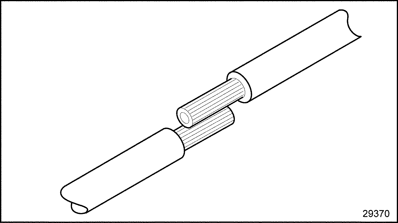
Figure 6. Positioning the Leads
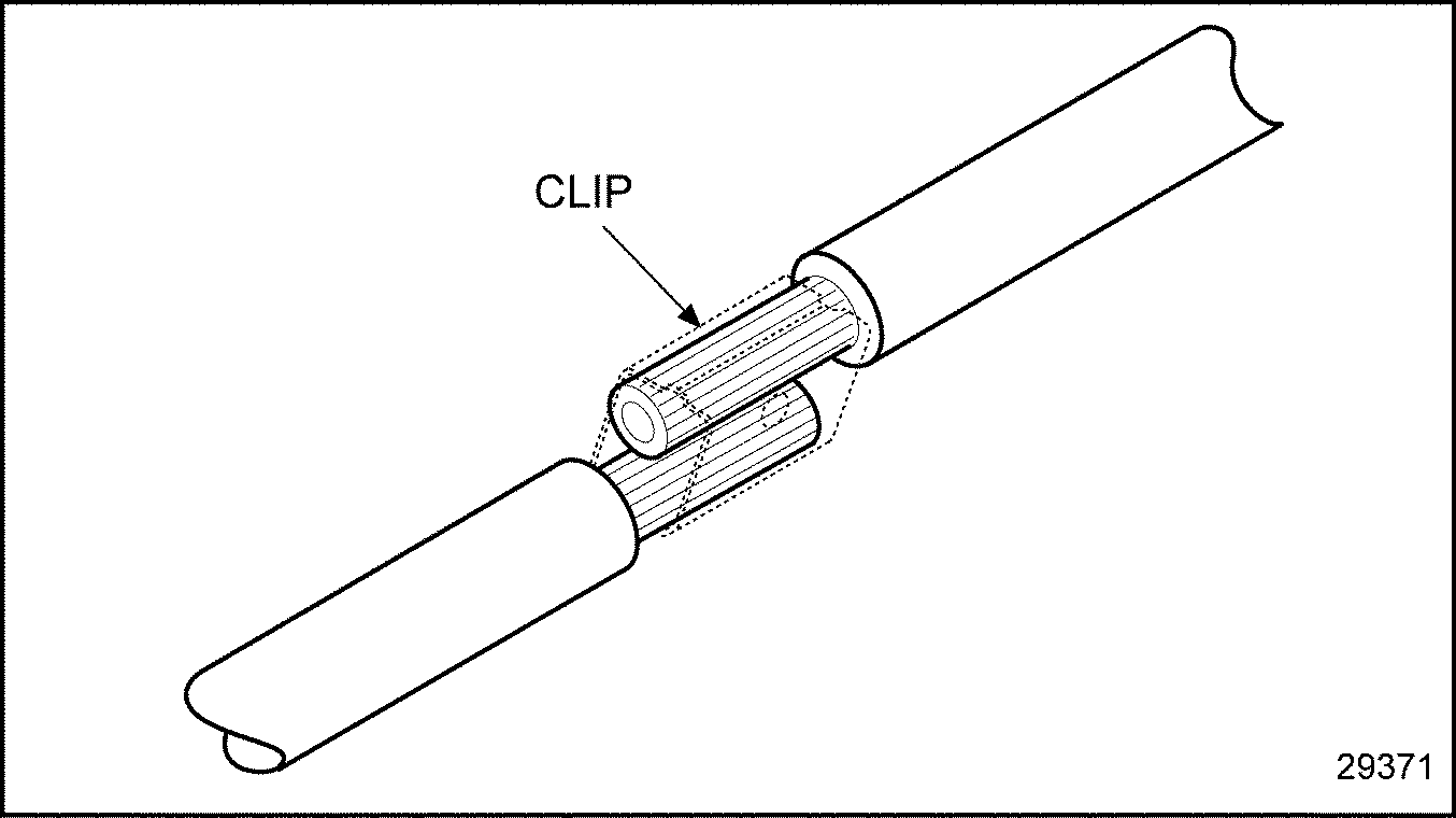
Figure 7. Securing the Leads With a Clip
|
Wire Gage |
Must Withstand Applied Load |
|
14 AWG |
45 lb (200 N) |
|
16 AWG |
27 lb (120 N) |
|
18 AWG |
20 lb (90 N) |
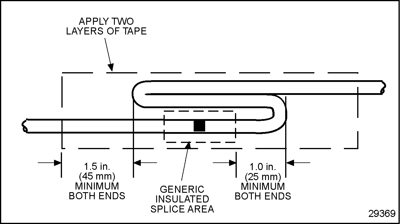
Figure 8. Recommended Strain Relief of Spliced Joint
The tools required are listed in Table "Recommended Splicing Tools" .
|
Tool |
Part Number |
|
Heat Gun |
-- |
|
Wire Stripper |
Kent-Moore J–35615 or equivalent |
|
Splice Clips (commercially available) |
Wire size dependent |
|
Heat Shrink Tubing |
Raychem HTAT or equivalent |
|
Terminal Crimper for Metri-Pack 280 (12 AWG) |
Kent-Moore J–38125-6 |
|
Terminal Crimper for Metri-Pack 280 (18 AWG) |
Kent-Moore J–39848 |
|
Terminal Crimper for Weather Pack |
Kent-Moore J–35606 |
|
Terminal Crimper for Deutsch |
Kent-Moore J–34182 |
|
Terminal Crimper for Metri-Pack 150 |
Kent-Moore J–35123 |
Note: When splicing straight leads, no more than one strand in a 16 strand wire may be cut or missing.
The recommended method to splice straight leads follows:
NOTICE: |
|
Any terminal that is cracked or ruptured is unacceptable as malfunctions may occur. |
|
Wire Gage |
Must Withstand Applied Load |
|
14 AWG |
45 lb (200 N) |
|
16 AWG |
27 lb (120 N) |
|
18 AWG |
20 lb (90 N) |
Shrink the splice clip insulative casing with a heat gun to seal the splice (see Figure "Splicing Straight Leads - Alternate Method 1" , C).
NOTICE: |
|
Splices may not be closer than 12 in. (.3 m) apart to avoid degradation in circuit performance. Replace wire to avoid having splices closer than 12 in. (.3 m) apart. |

Figure 9. Splicing Straight Leads - Alternate Method 1
This method is not allowed or recommended for power or ignition circuits. The tools required are listed in Table "Recommended Splicing Tools" .
|
Tool |
Part Number |
|
Heat Gun |
-- |
|
Wire Stripper |
Kent-Moore J–35615 or equivalent |
|
Splice Clips (commercially available) |
Wire size dependent |
|
Heat Shrink Tubing |
Raychem HTAT or equivalent |
|
Terminal Crimper for Metri-Pack 280 (12 AWG) |
Kent-Moore J–38125-6 |
|
Terminal Crimper for Metri-Pack 280 (18 AWG) |
Kent-Moore J–39848 |
|
Terminal Crimper for Weather Pack |
Kent-Moore J–35606 |
|
Terminal Crimper for Deutsch |
Kent-Moore J–34182 |
|
Terminal Crimper for Metri-Pack 150 |
Kent-Moore J–35123 |
Note: When splicing straight leads, no more than one strand in a 16 strand wire may be cut or missing.
An acceptable option for splicing straight leads is:
Insert one wire into splice clip until it butts against the splice clip. Stop and crimp (see Figure "Splicing Straight Leads - Alternate Method 2" , B).
Insert the remaining wires into the splice clip one at a time until each butts against the splice clip; stop and crimp (see Figure "Splicing Straight Leads - Alternate Method 2" , B).
NOTICE: |
|
Any terminal that is cracked or ruptured is unacceptable as malfunctions may occur. |
NOTICE: |
|
A minimum of two layers of heat shrink tubing must be applied to splices that have more than one lead in or out. |

Figure 10. Splicing Straight Leads - Alternate Method 2
Shrink wrap is required when splicing non insulated connections. Raychem HTAT or any equivalent heat shrink dual wall epoxy encapsulating adhesive polyolefin is required. Shrink wrap must extend at least .25 in. (6 mm) over wire insulation past splice in both directions.
To heat shrink wrap a splice:
NOTICE: |
|
The heat shrink wrap must overlap the wire insulation about .25 in. (6 mm) on both sides of the splice. |
Position spliced wires properly as follows:
NOTICE: |
|
You must stagger positions to prevent a large bulge in the harness and to prevent the wires from chafing against each other. |

Figure 11. The Correct and Incorrect Method of Staggering Multiple Splices
NOTICE: |
|
A minimum of two layers of heat shrink tubing extending .25 in. (6 mm) past the splice must be used to complete the splice. |
| EPA07 Series 60 DDEC VI Troubleshooting Guide - 6SE567 |
| Generated on 10-13-2008 |